G.8032 is an Ethernet switching protocol, also known as ERPS or R-APS. It basically does just one thing – allows easy ring topology without traffic loops.
R-APS is built on existing CFM monitored VLAN, that is used as a control VLAN. Management traffic over this VLAN can be sent everywhere and it is R-APS stack responsibility to manage the control traffic over this VLAN, so traffic loops don’t happen. The same CFM configuration can still be used for monitoring and control (Sending loopback, link-trace and issuing SAA tests between switches).
There are few terms that need to be understood, before we continue:
- CFM level on which G.8032 ring is built. Needs to be one and the same CFM Domain everywhere (same level, same domain name, same maintenance association name, same VLAN).
- Control VLAN is the same VLAN monitored by the CFM domain.
- Monitored VLAN(s) are a group of VLAN(s) that will be used in the ring for user traffic.
- Ring ID is the unique identification of the ring. It is also embedded in the R-APS control frame sent between units.
- Node Role is the role of any specific switch or router in the ring. They are either [Simple, RPL owner, RPL neighbor or Interconnection] node.
- Timers are meant to protect the ring from connection flapping and have nothing to do with performance.
- RPL stands for Ring Protection Link and is the link between RPL nodes, that is normally NOT allowing traffic to pass.
- Subring is a ring attached to an existing Ring, and using the same CFM level and configuration as the main ring.

A R-APS ring with a Subring and 3 customers.
Having a look at the diagram, we can tell that this is one main ring, with one subring and 3 users attached to various parts of the 2 rings.
R-APS Cons
- The protocol is suitable for rings only. Layer 2 mesh and star topologies are covered by other switching protocols, such as MSTP or RSTP.
- Optimal ring nodes in a ring is 4 (it is tested with up to 8 units, but the convergence timing suffers)
- Ladder type networks are possible (More rings, attached to each-other) but the topology changes propagation takes time to reach end rings and traffic loss is possible in large networks.
- Ring convergence (switching on demand or failure) is as good as the CCM hello interval used in the CFM configuration.
- It needs detailed Layer 2 CFM knowledge to build it on.
- Needs re-configuration of 2 ring nodes when adding another node in existing ring.
- Not always giving end-users the most optimal routes (user1 and user2 in the diagram above will have their traffic go sw6<->sw3<->sw2<->sw5<->sw4)
R-APS Pros
- Much easier to understand than xSTP and MPLS.
- Neat looking in a diagram. Less cables and connections to follow.
- Easy to add more rings to existing ring.
- In a good setup, convergence is <50 ms.
- Once built, the existing CFM configuration can be used to issue loopback, linktrace and SAA tests to check for delays, traffic bottlenecks and possible problems.
- Monitoring and control is much better than in xSTP or MPLS (CFM can be added there too, but not by default).
R-APS Node Roles

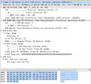
Captured R-APS frame in Wireshark
- Simple node is the node, that is simply connected to 2 other nodes. They are either other simple nodes or RPL nodes.
- Interconnection node is a node, that is connected to 3 other nodes. Interconnection nodes connect one ring to a subring. Interconnection nodes are very often connected to RPL nodes, but not always (depending on ring size).
- RPL-Owner node is the node that owns the RPL link. The RPL owner role in the ring is to send control R-APS packets towards the other nodes. R-APS packets are having few important parameters (see dissection in the picture). If you are interested in the packet itself, feel free to download and examine. The most important are the R-APS state and the request.
- RPL-Neighbor has almost the same function as the owner. It holds control over the other ring port that is part of the RPL link. Normally RPL-Neighbor holds this port blocked for all traffic except CFM on the same level and reacts to R-APS control frames with unblocking or blocking this port.
All nodes are passing CFM and R-APS frames to the next node through the ring link. If the node is an Interconnection node, it sends the R-APS packets only to the node in the main ring and blocks all subring R-APS frames, so they don’t loop the main ring.

Interconnection R-APS node
CFM Configuration.
It is a good practice to plan the CFM configuration in advance.
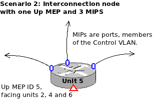
You may either stick with Down or Up MEPs (or both). Easier and more quick for configuration is to use Up MEPs, because you only set one MEP per unit.
In this case, the CFM MIP creation policy must be set to allow MIP creation for all members of the Control VLAN chosen for the R-APS ring – Otherwise the CFM connectivity will not be established.
But using Down MEPs is the most common practice.
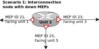
You set a ring port to be also Down MEP facing the neighbor unit. This way the CFM connectivity is established by pairs of MEPs facing each other.
This setup type is of course a bit more time consuming and harder to understand than using Up MEPs.
In our QA practice, we use numbering like MEP 21 (Switch 2 to Switch 1) or MEP 23 (Switch 2 to Switch 3) for easier mapping of the pairs, and we still make mistakes after months of practice (See Scenario 1 diagram).

R-APS node with one Up MEP and 3 MIPs
There are also some Pros and Cons about the Up MEPs.
Easiness is one of the good parts, and you can also use the much more open visibility between all MEPs to issue Linktrace and Loopback tests between units. (All Up MEPs will see all other Up MEPs)
With this setup you can find bugs in the network or bottlenecks in the route between random 2 switches.
In the same time, using a very rapid Hello Interval with Up MEPs (e.g. 3.3 ms) can have a heavy impact over the Switch CPU utilization, because you need to work with 300 CCMs per second per remote MEP. And this is quite a lot CPU overhead for bigger ladder networks. (6 Up MEPS generate total of 1800 packets per second, heard by all 6 switches in the 2 rings diagram above).
It is up to you to decide if you stick with Up or Down MEPs when building a G.8032 Ring network. Just plan ahead and plan smart. An example CFM configuration will look like this:
oam
 cfm
  domain d1
   level 1
   ma ma1
    vlan           1000
    hello-interval 300Hz
    mep 21
     bind-to     1/1/1
     no shutdown
     ccm-enabled
     exit
    !
    mep 23
     bind-to     1/2/1
     no shutdown
     ccm-enabled
     exit
    !
    mep 25
     bind-to     1/3/1
     no shutdown
     ccm-enabled
     exit
    !
    exit
   !
   exit
  !
 !
!
It is not really something complicated, once you get used to CFM. And it is also set-and-forget type of configuration. You don’t need to touch anything if the network topology is not changed.
For a normal setup with Down MEPs, it takes a bit of planning and charting, so you don’t get lost. You need to know all MEP pairs between ring ports in advance, so you better chart a bit. I use a neat useful Linux software called Dia (Diagram editor) which saves me tons of head scratching 😉 (actually most of my tech blog stuff is made with Dia).
When you set all units the way you planned, you need to see stable CFM connectivity on all MEPs in all Ring nodes. (except one intentionally broken link, so you avoid L2 traffic loops). If you don’t have CFM connectivity, the ring (of course) will not work.
The setting of the ring itself, when you already know what MEP is facing which MEP is quite trivial. Here is how a Telco Systems 7124s switch configuration looks like:
ethernet
 ring-aps
  instance 1
   role                  rpl-owner
   control-vlan          1000
   monitor-vlan 1
   monitor-vlan 2000
   cfm-domain-level      1
   wait-to-restore-timer 1
   port 0
    port-id  1/1/1
    mep      12
    rpl-port
   !
   port 1
    port-id 1/2/1
    mep     52
   !
   no shutdown
   subring 2
    control-vlan               1000
    subring-port 1/3/1
     mep 62
    !
    ring-id                    2
    virtual-channel-vlan       2000
    wait-to-restore-timer      1
    propagate-topology-changes
    no shutdown
   !
  !
 !
!
Very important: When you build L2 rings with MSTP or R-APS, build them with one of the ring links intentionally broken.
When all your RING units are set and enabled, restore the link connection.
This way you will not make a traffic loop with control packets before the ring is operational.
If you set everything okay in this example, you will have CFM connectivity on level 1 with 3 local MEPs connected to 3 remote MEPs. R-APS needs about 1 minute (with the example setup) to initialize and get Up.
And the result will look like this:
===============================================================================
RING APS Detailed Information
===============================================================================
------------------------------------------------------------------------------
Ring 1 Instance 1 Role rpl-owner
------------------------------------------------------------------------------
Admin State - Up                Oper State       - Up
RAPS State  - Pending           Top Priority cmd - N/A
Control VLAN- 1000              Revertive Mode   - Enabled
Hold-off timer (msec)- 0        Wait-to-restore timer (min)- 1
Guard timer (msec)- 500         Wait-to-block timer (msec)- 5500
Monitored VLANs- 1,2000

Port 0 - 1/1/1
    Role         - RPL                Status - Up
    Peer Node ID - 00:01:6C:27:4B:BA  Peer Mep - 12
    Peer Command - N/A                Peer Info -
Port 1 - 1/2/1
    Role         - Regular            Status - Up
    Peer Node ID - 00:01:6C:27:4B:BA  Peer Mep - 52
    Peer Command - N/A                Peer Info -
-----------------------------------------------------------------------------
Ring 2 SubRing 2 Role simple-node
-----------------------------------------------------------------------------
Admin State - Up                Oper State       - Up
RAPS State  - Pending           Top Priority cmd - N/A
Control VLAN- 1000              Revertive Mode   - Enabled
Hold-off timer (msec)- 0        Wait-to-restore timer (min)- 1
Guard timer (msec)- 500         Wait-to-block timer (msec)- 5500
Virtual Channel VLAN - 2000
Propagate Topology Changes - Yes

Port - 1/3/1
    Role         - Regular            Status - Up
    Peer Node ID - 00:06:4F:29:49:F0  Peer Mep - 62
    Peer Command - N/A                Peer Info -
Virtual Channel
    Peer Node ID - 00:01:6C:E2:FF:D2
    Peer Command - N/A                Peer Info -
===============================================================================
Troubleshoot R-APS
It happens to make errors in configuration. Sometimes even good planning leads to something missed. This is quick Q&A to check, in case you don’t have the results you want:
- Do you have CFM connectivity between all your ring nodes?
- Did you set all CFM domains and associations with the same parameters? (names, level, VLAN)
- Did you set all Ring nodes working on the same CFM level?
- Did you set the remote MEP IDs expected on port 0 and 1 exactly as planned? (very common mistake)
- Is your Control VLAN set the same everywhere? (Same as CFM MA configuraion)
- Are your node roles set correctly? (One RPL-O, one RPL-N, few simple nodes)
- Did you set the RPL ports exactly between owner and neighbor nodes?
- Is your RingID same on all members of the ring?
- Is the subring RingID different than main ring RingID?
- Do you monitor all VLANs involved in sending traffic in all ring nodes? (Missed monitored VLAN on any node does not get stopped on ring ports and leads to L2 traffic loop)
- Do you monitor the default VLAN? (easiest L2 traffic loop is management traffic sent on the default VLAN such as SNMP or telnet)
- Do you send management traffic over the Control VLAN different than CFM traffic?
- Are your timers the same on all ring nodes?
- Did you forget to enable any Ring node? R-APS gets established (state: Up) and blocks user traffic, only when it is working (administratively Up).
- Are your ring ports Up? (you may forget to wire them sometimes. It happens. Don’t worry.)
If you answer any of the questions above with “Yes” – then you probably have broken ring or massive traffic loop. Check port status and statistics. Without user traffic, you should see only the CCMs flowing between ring ports (600 p/s in the CFM configuration above). Recheck if the CFM connectivity is okay everywhere. R-APS depends solely on well working CFM.
Test R-APS
When everything is set, you may check some simple tests to see if the rings are working fine.
- Execute Linktrace between Site1 and User1. You should see the linktrace pass sw1 -> sw2 -> sw3 -> sw6.
- Execute Linktrace between Site1 and User2. You should see the linktrace pass sw1 -> sw2 -> sw5 -> sw4.
- Break the link between sw2 and sw5.
- Execute Linktrace between Site1 and User2. You should see the linktrace pass sw1 -> sw4.
- Break the link between sw2 and sw3.
- Execute Linktrace between Site1 and User1. You should see the linktrace pass sw1 -> sw4 -> sw5 -> sw6.
- No traffic should be lost while you do the link breaking tests. R-APS will enable the RPL links in less than 50 milliseconds. Normal user traffic must not feel it at all.
If all of the above is checked to work – then CONGRATULATIONS! You’ve just made your first working pair of Rings.


